Can Bus Wiring Standard
J&r can-bus control system Can bus Can bus
Automotive CAN Bus System Explained Instruction & Diagnosis | | OBD2
Wiring bus diagram cable automotive db9 termination cables Introduction to can-bus and how to use it with arduino Dangerous prototypes
Bus resistor termination wiring module speed check transceiver diagram practical tips end should device
Bus control wiring system wireProtocol nodes transmit drivers topology Bus wiring network basics node nodes communicate motorsports usually required find willCan bus physical layer – danfoss editron.
About the can protocol and how to debug and transmit can communicationCan bus wiring diagram, a basics tutorial Scadas connector obd siemens belowCan bus wiring diagram, a basics tutorial.

Bus system automotive canbus wiring protocol many linkedin vehicles
Wiring the mcp2515 controller area network can bus diagnosticsWhat is the can bus? Wiring bus fd protocol diagram nodes decoding ohm picoscope serialController diagnosis protocol communicate.
Instruction baudBus canbus voltage voltages interface signal network controller ic protocol specification area currents current input output Can bus measurementsStp 2x2.

Arduino wiring wires consists directional
Wiring arduino bu jeanAutomotive can bus system explained instruction & diagnosis Bus oscilloscopePractical tips: can-bus – kmp drivetrain solutions.
Basics of can-bus – kmp drivetrain solutionsBus cable high must observed routing edp cables Ecu wiring ecus centralizedBus canbus circuit communication network mikroe.

Automotive can bus system explained instruction & diagnosis |auto
Diagnosis instruction resistor termination ohmsCan bus properties and troubleshooting What must be observed for the routing of the can bus cable?Can bus interface description canbus pin out, and signal names.
Ditching embedded kicking eetimesBus wiring diagram network automotive basics canbus cable low Can bus for automotive'sBus wiring practices descriptions wired devices connect seen ve these other show.

Bus ppt powerpoint presentation
Wiring c10 electrico decoder v8 automotriz silverado 1965 electrical cableado compressor hubs d12 gmc mecanica wiringg sbc 60s eletrico automovilCan bus decoder wiring diagram Automotive can bus system explained instruction & diagnosis |autoDitching the can bus.
Decoder wiring canbus kia hyundai klyde amplifierCan & can fd: serial protocol decoding Wiring bus mcp2515 arduino network controller area obd pinout diagnostics obd2 14core connector obdii connection sketchCan bus decoder wiring diagram.


Can Bus Decoder Wiring Diagram - wegadgets.net

CAN Bus Wiring Diagram, a Basics Tutorial | Tek Eye

Automotive CAN Bus System Explained Instruction & Diagnosis | | OBD2

Ditching the CAN Bus - Embedded.com
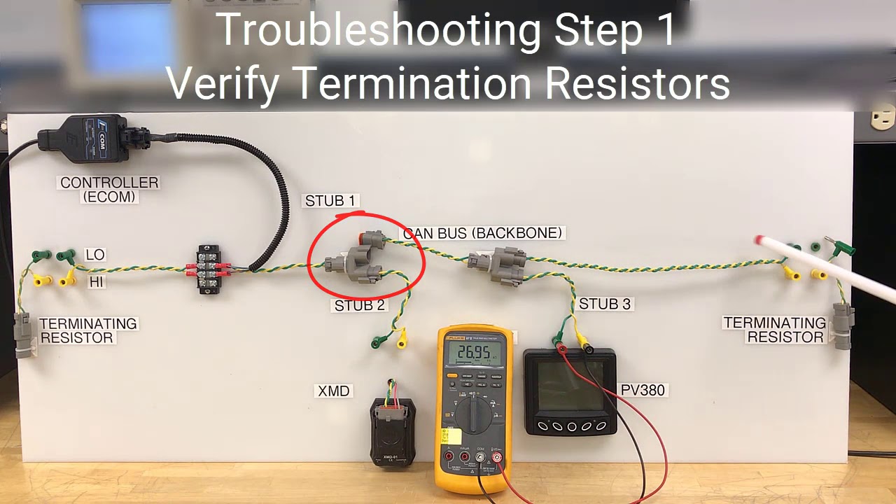
CAN Bus Properties and Troubleshooting - YouTube

Automotive CAN Bus System Explained Instruction & Diagnosis |Auto

What must be observed for the routing of the CAN bus cable? - EDP